A Linear Matched Independent Current Source
The LDO linear regulator topology of the TPS7510x (as Figure 1 illustrates) lends itself to many advantages over traditional fixed-mode and mixed-mode charge pumps as well as inductive boost converter topologies. The TPST510x is a highly effective alternative to these solutions in many applications. It provides a significant cost savings over all of the alternatives by reducing or eliminating many external parts. This reduction not only limits bill of material costs, but also the additional manufacturing costs of placing the extra components, which often can be $0.01 to $0.02 per component.
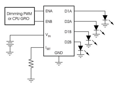
Figure 1.
Another benefit to the reduced component count is reduced solution size. Because the TPS7510x require no external components, the total solution size is reduced to just the size of the IC, which is 1.44rnm2 for the WCSP package. A third advantage to the TPS7510x is that nearly all of the input current (99%) is used to drive the LEDs; the current is not lost on charge pump capacitors or boost inductors. This power-saving architecture increases the average efficiency over the battery discharge life to more than 87%. At a nominal battery voltage of 3.6V, the efficiency of this solution is typically greater than 99%. The most critical disadvantage to the LDO topology is that the foward voltage of the LED is limited to the input voltage minus the dropout (30mV typical, 100mV max). This limitation is no longer a major drawback because there are several white LEDs available today that have forward voltages of typically 3V or less at the LED current levels used in mobile solutions (3mA—10mA). A second well-documented limitation to the linear solution is that it is only useful in parallel LED configurations. Series configurations would result in too great a forward voltage demand for standard, single-cell Li-ion battery applications. The TPS7510x solution is limited to parallel LED configurations.
In applications where a fixed-boost charge pump is used (see Figure 2), the output is boosted to a fixed voltage and the LED current is regulated through individual resistors. This method is relatively inexpensive as a result of the low cost of charge pump devices, but the LED current matching and efficiency can be very poor (43% average over battery discharge). The one key advantage of the charge pump is that it reduces the dependency of the forward voltage of the LED to the supply voltage (within a few volts of the supply rail). However, because a charge pump that generates voltages large enough to drive multiple LEDs in series is highly inefficient and costly, this solution is commonly limited to parallel LED configurations.
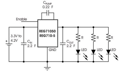
Figure 2. Fixed-Boost Charge Pump(REG710)
The TPS?510x provides an efficierlcy boost in these types of applications as well as a cost savings from the decreased overall oomponent count, but is limited to forward voltages being lower than the supply.
Mixed-Mode Charge Pump
In applications where a mixed-mode charge pump is used (as Figure 3 shows), the output voltage is regulated to maintain a constant current through each LED. The LED current sources for these lGs can be well-matched because of the topology used in this type of solution. However, actual matching is degraded by any mismatch in forward voltages. These circuits are moderately efficient (70% average over battery discharge) and also allow for forward voltages greater than the input.
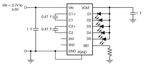
Figure 3. Mixed-Mode Charge Pump (TPSI-30231)
The TPST51Ux presents significant cost and efficiency improvements over these applications. The charge pump circuits usually require one or two switching capacitors as well as input and output capacitors for stability. As noted earlier, the decreased component count of the TPS7510x reduces the size of the solution as well as the cost. The downside of the linear solution relative to the mixed-mode charge pump solution is the LED forward voltage (headroom voltage) limitation. However, the mixed-mode charge pump solution can be well-matched with identical LED voltages; the TPS7510x is well-matched, regardless of the variation in the LED forward voltages.
Inductive Boost
In applications where an inductive boost converter is used (most commonly to drive a series string of LEDs), as shown in Figure 4, the LED current is identical (ideal current matching) through each of the LEDs in the string. As with charge pump solutions, LEDs with a forward voltage greater than the supply voltage can be used. ln some applications—such as backlit LCD modules in clamshell-style handsets~—where only a single LED drive line is available, the inductive boost converter is often the best (and occasionally, the only viable) solution.
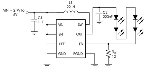
Figure 4. Inductive Boost (TPS61061)
In other applications where electromagnetic interference (EMI) caused by the inductive switcher could present a problem, the linear TPS7510x can be an effective, extremely low~noise alternative. In addition, the cost savings achieved by eliminating the inductor, output capacitor or feedback resistor can be substantial.
With the extensive range of applications for white LEDs in mobile handsets, driving these LEDs is no longer restricted to a single high-voltage, high-current solution. Solutions are now as varied and numerous as the applications for these devices. The recent advent of brighter, more effiicent, white LEDs that can be driven with lower current opens up a new solution using linear current sources. This solution provide the lowest cost, fewest component counts, and smallest solution size available, ideal for mobile handset applications. |